
Custom Cyclone Dust Separator
– or –
Falling down a rabbit hole over 9sqft of floorspace
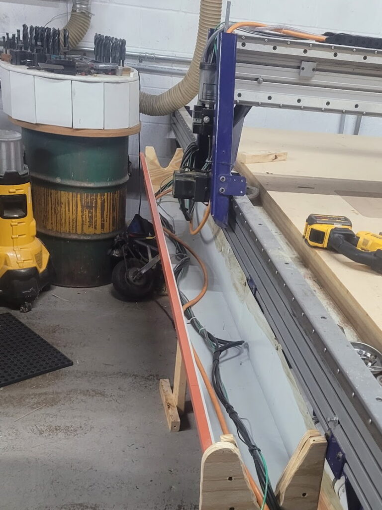 Also, cable tray! It’s not stupid if it works | [Downloads at bottom of Page] We’re looking at some new equipment for the space, which means… we need more room! We found a fair bit re-organizing, but this dust collection barrel caught our eye. Look at this barrel: -Ugly -Inefficient -So much floorspace |
This barrel is the first stage of dust-collection for our CNC – Air and dust come in one side, dodge past some vertical baffles, and exit to our main dust-collector for further filtering. Theoretically, the heaviest dust should fall into this barrel and be trapped, and over a few years of use it caught probably 20% of our sawdust. More importantly, it’s on the ground, and that’s space we could use for more tools!
Design:
The first thought was just to put it on legs. But if we’re going to go through the work of building a stand for it, maybe it’s worth redesigning the system! And thus, I began researching dust collectors. I originally intended to make a transparent baffle system – smaller, clear so you could watch, better baffling – but essentially the same thing. But the research said cyclones were the best, and I fell in love with the idea for sheer cool-points.
So I searched high and low for cyclones that fit our shopbot and dust-collector flow, but they were all opaque plastic or thousands of dollars. We don’t have 5 grand to spend on cool-points, so that meant some fabrication if my heart was set on watching the dust swirl. First idea! We can modify an existing clear cone that’s generally the right size. Nope, still 1000s of dollars.
At this point I was at a loss, and booted up chatGPT for some rubber-ducking. This started with general size and flow recommendations, before exploring alternate geometry… Would a cylindrical cyclone work? It would work well enough – but 8″ lexan tubing was also prohibitively expensive…. what about a polygonal prism mimicking a tube? How many faces do I need to be 90% as efficient? 95% as efficient?
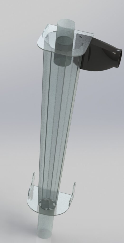
That’s when I realized I could switch the faces to trapezoids and approximate a transparent cone. From there, it was on to questions about injector dimensions/geometry/angle, exhaust port depth, and learning the ins and outs of cyclone design.
With a notepad full of dimensions and key features, it was off to CAD, where I set about constructing the cyclone and adjusting the design for manufacturability, mounting, etc. The end design was going to cost $380 at send-cut-send. Definitely more than I expected to pay when I started this, but I was too deep now.
I wasn’t quite ready to risk $400 on advice from a robot, so I sent my design out to other members at the hackerspace, and booted up grok to see if it would agree. After letting the gpts fight a bit (confirming assumptions, airflow, etc) they agreed it would definitely be more efficient than the old barrel, maybe much more efficient, and none of the humans saw any major flaws. So I dropped my orders, and after a few days 17 pieces of polycarb were on their way to the shop.
Theory
A quick primer on cyclone theory: The dust/air enters at the top, tangential to the walls of the cyclone. This induces a rotation, as the air/dust will begin to spin around the cyclone. The exhaust port needs to be lower than the injector – or at least lower than most of it – this forces the spiral and prevents the dust from short-circuiting the spin and heading straight up the tube.
Once the rotation is established, the dust is all flung towards the outward walls due to centrifugal force. Even though the dust is exceptionally light, it’s still heavier than the air, and an initial airspeed of 80mph means we have about 1000g’s of force pulling this dust outward once we hit the cylinder. This tornado of dust and air begins to descend down the cylinder, losing speed as some of the central (cleaner) air is sucked out the exhaust port on top. This is where the cyclone shape shines: Despite the air slowing, the shrinking diameter keeps the momentum up, keeping the dust flung out to the edges.
Finally, the tornado loses too much speed to keep the dust in the air, and the dust falls to the collection chamber below.
Construction
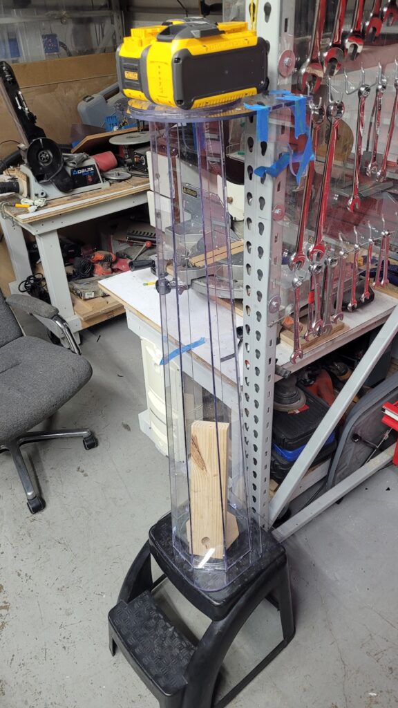
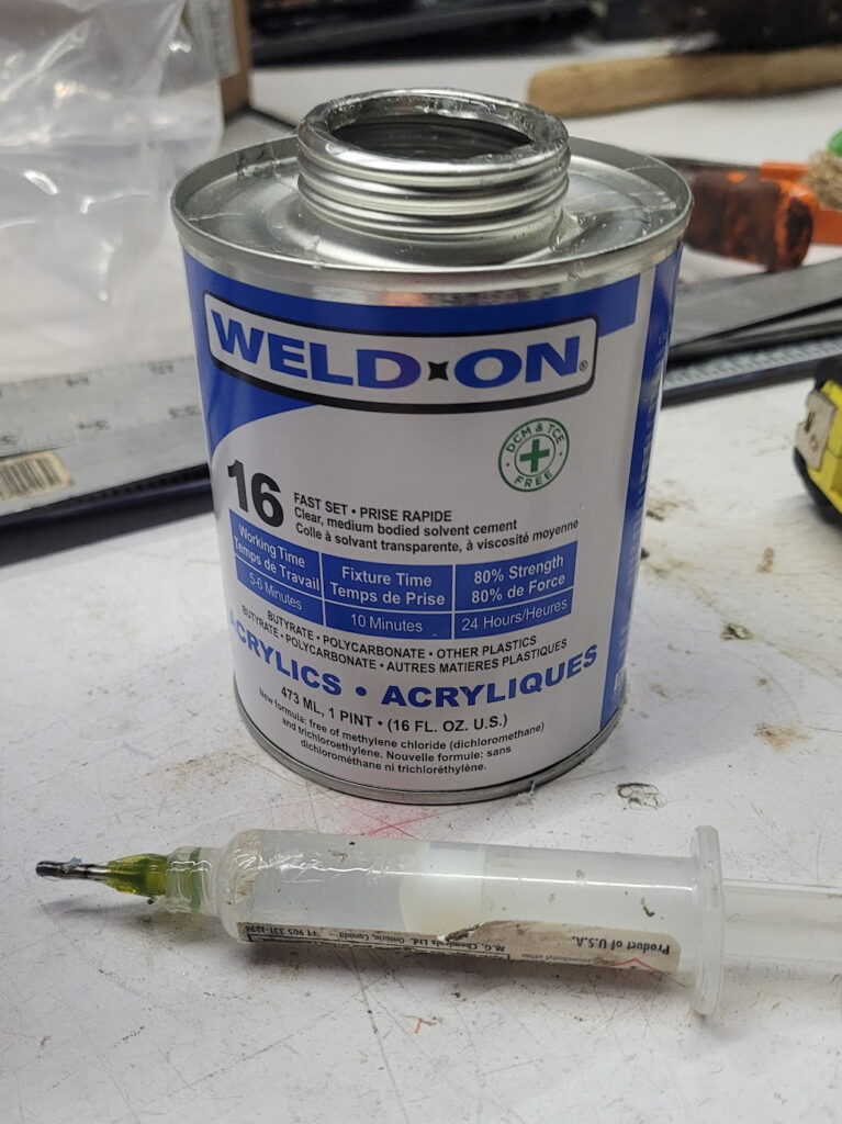
Now that all my parts are in, time for construction! The whole thing has to be glued together. I’m using WeldOn 16 (because chatGPT told me to) which is incredible at bonding Lexan. The glue-up was…. fiddly. I needed all the side panels to fit together at once, and one always fell out as I inserted the last few pieces. I ended up lasercutting a few temporary octagons to brace the sides, and had a friend help with a second set of hands while I got the first dots of glue in. Once it was partially glued, the rest went a treat, though somewhat slowly – I spent over 4 hours building the main cyclone body. Dribble a few drops of glue into a crack, move to a new spot, and repeat until there’s full coverage – I highly recommend a syringe for this so you can get the glue right where you want it and minimize drips / stringing (static cling is wild on this much lexan). A few of the trickier corners got a few dabs of silicone as well, just to make sure everything was truly airtight.
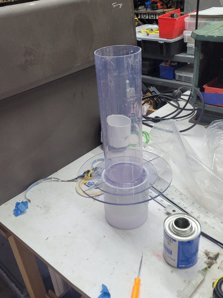
With the body assembled, it came time for the 3d bits. I printed the inlet adapter in PETG, and cut out a port for it to attach to at the top of the sidewall. If you’re building your own from these plans, please pick the appropriate adapter from the download file to bias air correctly.
The next 3d bits were the chamfers. A few internal chamfers at the top help establish the swirl early, improving efficiency. I embedded a copper wire in my chamfers, which will bleed static electricity, which should reduce friction from the dust sticking to the wall, also improving efficiency. These were glued in with the magic of WeldOn 16.
The only other non-plastic part was the lid gasket. I wanted to have access to the interior for cleaning and repairs, so I made the lid removable. A thin rubber gasket, etched with the laser cutter and cut with scissors, makes sure no air can leak through (especially important if you’re running ground-lines under the lid). In my build, I ended up clamping this lid on with clamps, but I’ve included boltholes in the updated models. You don’t need all eight bolts – in operation, the suction will hold everything in place, these are just in case the hoses tug the lid open.
Finally, I glued the collection pipe on. In retrospect, I regret this. I should have glued a threaded adapter to the bottom for more flexibility, better cleaning, easier mounting, etc…. but I was in love with clear and PVC isn’t clear. I did add a threaded adapter to the bottom for a clean-out plug. The weld-on appeared to be holding well enough, but it was such a tiny seam I glued in a 3d printed chamfer (externally) for some extra glue area.
Links/Downloads
Full download:
- This contains all DXFs, all STL files, and all the full solidworks assembly.
- I could split this by process, but I truly can’t be arsed
- DXF filenames include quantity to order.
- Except for the gasket, all parts should be 0.22″ (5.88mm) Polycarbonate
- Left and righthanded injectors included. The cyclone doesn’t care, layout might
- Bambu print files included, but,
- Please use this link so we can get some free filament:
- Also, you’ll need two of these pipes: 4×36 clear tube
- And a can of WeldOn 16 (Please please please click this link regardless)
Results:
It was finally time to kick this on and see what happened. I was terrified it would immediately implode – there’s a lot of stress compressing this prism. A few of the members rallied around for support, and we hit the suck button. Immediately, we saw air swirl in and clean the top half of the cylinder, and as the CNC started cutting, a small band of chips orbited the top while the base tube started filling with dust.
Rough math (volume of dust * packing ratio / volume of material removed by CNC) is putting us just above 90% efficiency. This is significantly better than the previous barrel, and the quality of the dust (much of it is ultra-fine and very flammable, opposed to the flakey dust we used to get from the barrel) supports that hypothesis. The only downside is it means our dust reservoir needs to be drained after every major CNC session.


